Technical Information
Defects and Countermeasures
Nitrile Rubber Packing
| Phenomenon | Conditions | Causes | Countermeasures |
|---|---|---|---|
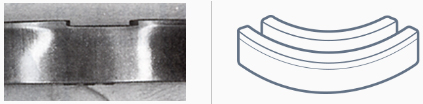
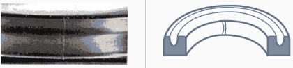
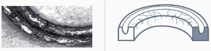
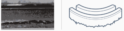
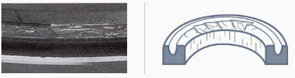
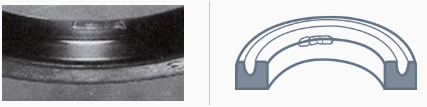
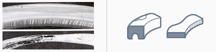
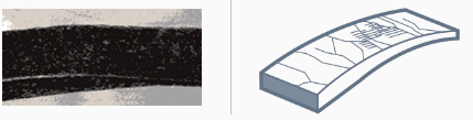
| Degradation |
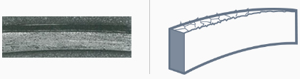
The entire sealing surface is hardened. Cracks are present on the glossy surface or appear when pressed with a finger. |
Heat generation due to high speed or excessive internal pressure. | For pistons, change to SPG or SPGW. For rods, replace them with a backup ring. |
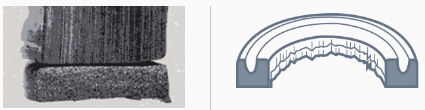
The entire packing is hardened, causing a significant collapse of the lip. Cracks appear when bent with a finger. |
The oil temperature is high. | Lower the oil temperature or change to heat-resistant material (fluoro rubber). | |
| Effects of oil Incompatibility between oil and rubber material Degradation of oil | Change to rubber material with good oil resistance. Change to a new oil. | ||
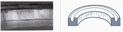
Small cracks occur across the entire packing surface. |
Ozone cracks are caused by leaving the packing exposed to air for an extended period. | Do not unnecessarily open the packaging; keep it sealed and store it in a cool, dark place. | |
| Ozone cracks are caused by leaving the packing mounted on the piston. | Do not leave it mounted on the piston; assemble it into the cylinder promptly. | ||
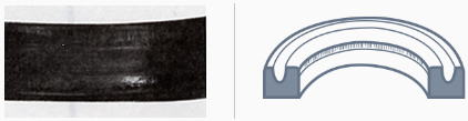
| Swelling |
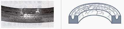
The entire material has become soft. |
Insufficient formation of the oil film during operation with a small stroke. | Change to rubber material with good oil resistance. |
| Effects of cleaning solution. | Change the cleaning solution. Remove the cleaning solution. | ||
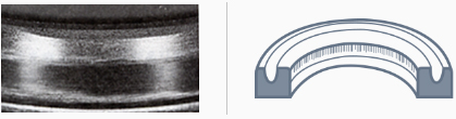
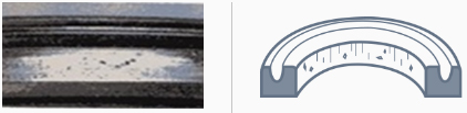
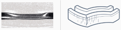
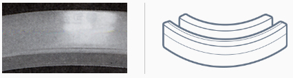
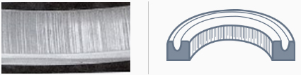
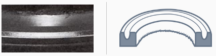
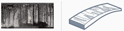
| Wear |
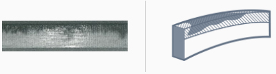
The operating surface is glossy and shows mirror-like wear. |
Insufficient formation of the oil film during operation with a small stroke. | For the piston, change to SPG or SPGW; for the rod, change the back-up ring. |
| Inappropriate surface roughness of the operating surface (surface is too smooth). | Change to the recommended thickness. | ||
The width of the operating section varies continuously along the circumference, with the positions of minimum and maximum width being almost symmetrical. |
Eccentricity between the rod and cylinder bed and between the cylinder and piston bed. | Control assembly eccentricity within the packing tolerance range. | |
A part of the operating lip circumference is severely worn (aligned with the lateral load direction). |
Excessive lateral load causing abnormal wear of the piston and bearing (rod). | Change wearing and bearing materials to those that can withstand the load. | |
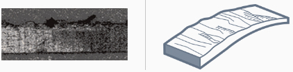
| Scratches |
There are partial dent marks on the lip edge. |
Damage caused by external forces during storage, such as hanging on nails, wires, or localized deformation. | Improve storage methods. |
| Insufficient chamfering of the mating part during assembly. | Enlarge the mating chamfer and smooth it to prevent flipping. | ||
| Damage caused by screwdrivers or similar tools during assembly. | Use assembly jigs. | ||
There are scratches on the operating surface. |
Scratches on the mating operating surface. | Perform thorough inspection before assembly. | |
| Perform thorough inspection before assembly. | Chamfer according to specifications and smooth to prevent flipping. | ||
| Embedded foreign particles. | Ensure proper cleaning. | ||
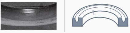
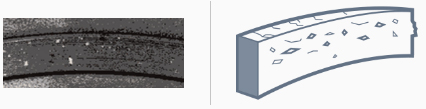
| Indentations |
There are small pit holes on the operating surface. |
Dust or cutting debris embedded due to insufficient cleaning. | Remove foreign particles attached to the equipment. |
| Foreign particles embedded in the oil or deposits formed by oil oxidation. | Replace with new oil. | ||
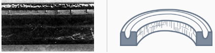
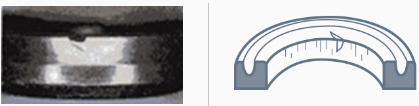
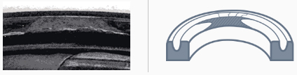
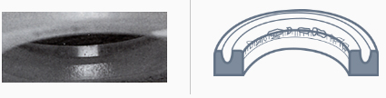
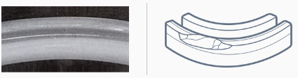
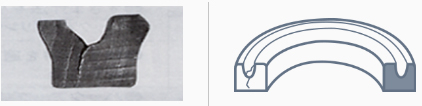
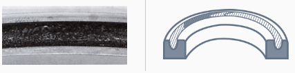
| Breakage |
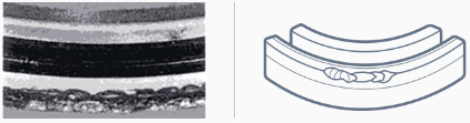
The packing’s operating lip is broken in an arc shape (piston seal). |
Excessive back pressure |
Change to OUHR. Change to SPG (SPGW). |
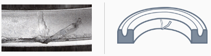
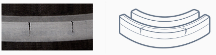
A crack originated from the packing groove. |
Frequent impulse pressure led to fatigue failure | For the rod, apply a buffer ring. For the piston, change to SPG (SPGW). |
|
| Fracture occurred during operation at low temperatures | Change to packing made of rubber material with good cold resistance. | ||
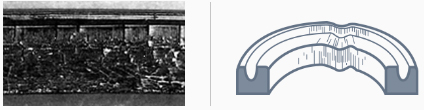
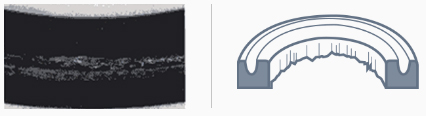
The operating lip is entirely broken. |
Frequent impulse pressure led to fatigue failure | For the rod, apply a buffer ring. For the piston, change to SPG (SPGW) |
|
| Fracture occurred during operation at low temperatures | Change to packing made of rubber material with good cold resistance. | ||
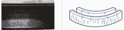
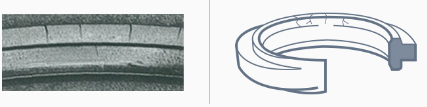
Breakage is found in 1–2 spots around the packing circumference. |
Packing was installed in a twisted state or assembled with improper installation conditions | Improve installation methods and installation tools. | |
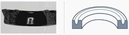
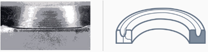
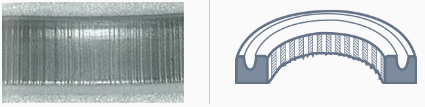
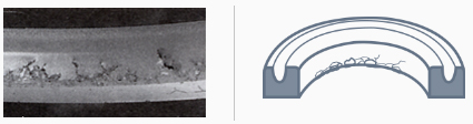
| Burn |
The lip and grooves are locally burned, carbonized, or melted. |
Burn damage caused by adiabatic compression of residual air. | When starting the hydraulic cylinder, fully bleed the air and avoid sudden full-stroke motion. If using a U-packing, fill the pocket area with grease to reduce air accumulation. |
| Extrusion |
The operating heel is torn. |
Excessive leakage clearance. |
Reduce the gap dimensions. Modify the back-up ring. |
| Severe bearing wear has increased the bearing clearance. | Change the bearing material to an appropriate one. | ||
| Excessive pressure | Modify the back-up ring and reselect the packing. Modify the back-up ring. | ||
The operating heel is torn. |
The groove structure of the equipment is inappropriate. | Adjust the chamfer section. | |
| Gaps formed due to insufficient strength of the retaining plate. | Increase the strength of the retaining plate. | ||
| The back-up ring is inappropriate. |
Adjust the dimensions of the back-up ring. Change the back-up ring material to the correct one. |
||
The packing operating heel and the back-up ring are extruded. |
Excessive leakage clearance. | Reduce the clearance dimensions. | |
| The back-up ring is inappropriate. |
Iron Rubber Packing
| Phenomenon | Conditions | Causes | Countermeasures |
|---|---|---|---|
| Degradation |
The surface is glossy, but it has cracks that appear when pressed with a finger. |
Excessive increase in oil temperature | Lower the oil temperature or change to a heat-resistant material (fluoro rubber). |
| Incompatibility between oil and rubber material | Check oil resistance and change the packing material or hydraulic fluid. | ||
| Oil degradation | Replace with new oil. | ||
The rubber has lost its elasticity and crumbles. |
Excessive increase in oil temperature | Change to a rubber material with good heat and oil resistance. | |
| Incompatibility between oil and rubber material | Check the oil resistance and change the packing material or hydraulic fluid as needed. | ||
| Oil degradation | Replace with new oil. | ||
The operating lip is entirely detached. |
Excessive increase in oil temperature | Change to a rubber material with good heat and oil resistance. | |
| Incompatibility between oil and rubber material. Oil degradation. |
Check the oil resistance and change the packing material or hydraulic fluid as needed. Replace with new oil. | ||
| Wear |
The operating surface is glossy and shows mirror-like wear. |
The operating surface is glossy and shows mirror-like wear. | For pistons, change to SPG. For rods, modify the back up ring. |
| A constant pressure of over 3 MPa is applied. |
For pistons, change to SPG. For rods,
modify the back-up ring. Check the piping resistance and modify the piping layout to achieve a low-pressure configuration. |
||
A part of the operating lip circumference is severely worn (aligned with the lateral load direction). |
Abnormal wear of the wearing ring (piston) and bearing (rod) due to excessive lateral load. | Change the wearing and bearing materials to ones that can withstand the load. | |
The operating surface is worn. |
When operating with a small stroke, the lubrication film is insufficiently formed, resulting in significant heat generation and a thin oil film. | If using a sharp lip, change to an R-lip type. Switch to a combination seal with excellent self-lubricating properties. For rod packing, add a buffer ring. | |
| Scratches |
The tip of the lip is partially torn or dented. |
Damage caused by external force during storage, such as hanging with needles or wires. | Improve storage methods. |
| Enlarge the chamfer of the mating part and make it smooth to prevent inversion. | |||
| Tears or dents caused by needles, screwdrivers, etc., during assembly. | Use assembly jigs. | ||
There are scratches on the operating area. |
Scratches on the mating operating surface. | Perform thorough inspection before assembly. | |
| Enlarge the chamfer of the mating area and make it smooth to prevent inversion. | |||
| Scratches caused by embedded foreign material. | Ensure proper cleaning. | ||
There are scratches on the tip of the lip. |
Scratches caused by the inversion of the chamfered edge of the mating part during assembly | Smooth the mating surface according to the dimension chart. | |
| Breakage |
The operating lip of the packing is extruded in an arc shape or torn (piston seal). |
Excessive back pressure. |
If using iron rubber packing, change to OUIS. Change to a combination seal (SPG, SPGW). |
Cracks originate from the groove of the U-packing. |
Fatigue failure due to frequent shock pressure. |
For rod packing, modify the back-up ring. For piston packing, change to SPG (SPGW). |
|
| Extrusion |
The heel on the operating side is torn. |
Excessive extrusion clearance. |
Reduce the clearance dimensions. Modify the back-up ring. |
| Bearing wear is severe, and the bearing clearance is excessive. | Change the bearing material to an appropriate one. | ||
| Excessive pressure. |
Modify the back-up ring and
reselect the packing. Modify the back-up ring. |
||
There are small indentations from the heel to the lip end on the operating surface, and a thin, film-like extrusion is attached to the heel area. |
Excessive extrusion clearance. | Reduce the clearance dimensions. Modify the back-up ring. | |
| Excessive pressure. | Modify the back-up ring and reselect the packing. Modify the back-up ring. |
||
The heel on the operating side is protruding and deformed, with the entire area discolored red. |
Excessive extrusion clearance. |
Reduce the clearance dimensions. Modify the back-up ring. |
|
| Severe bearing wear and increased bearing clearance. | Change the bearing material to an appropriate one. | ||
| Excessive pressure. | Modify the back-up ring and reselect the packing. Modify the back-up ring. |
||
The outer circumference of the pure PTFE back-up ring is torn, and the packing has extruded and deformed. |
Insufficient strength and wear resistance of the back-up ring. | Change the back-up ring material to 19YF or 80NP. | |
| Burn |
The groove of the U-packing is partially burnt and carbonized. |
Burning caused by adiabatic compression due to residual air. |
Bleed the air thoroughly when starting
the hydraulic cylinder. Do not move rapidly to full stroke. ‘If using U-packing, fill the pocket with grease to minimize air accumulation. |
| Deformation |
Deformation and damage in two places on the outer circumference. |
Improper installation in the groove. |
Combination Seals and Seal-related Products
| Phenomenon | Conditions | Causes | Countermeasures |
|---|---|---|---|
| Degradation |
Cracks in the back ring. |
Used under high-temperature conditions. | Replace the back ring with a material with excellent heat resistance. |
| Wear |
A part of the seal's circumference is severely worn (aligned with the direction of lateral load). |
Eccentricity caused by excessive lateral load and abnormal wear of the wearing or bearing. | Replace the wearing or bearing materials with ones that can withstand lateral loads. |
| The mating sliding surface is partially rough. | Finish the surface roughness uniformly (recommended value: 0.4–3.2 μm Ry). | ||
| Scratches |
Scratches on the operating surface of the rear front ring. |
Scratches on the mating operating surface. | Perform thorough inspection before assembly. |
| Burrs or flipping of the mating chamfer during assembly. | Chamfer the mating surface according to the specification table, ensuring it is smooth without burrs or flipping. | ||
| Embedded foreign matter (e.g., metal powder). |
Remove foreign matter. Design a contamination seal (KZT) on both sides of the packing. |
||
| Extrusion |
There is a film-like extrusion on the seal operating surface. |
Large leakage clearance. High pressure. |
Reduce the clearance. Change the material to one with higher rigidity. Use SPGW with a back-up ring attached. |
| Indentation (foreign matter embedded) |
Foreign matter is embedded in the seal and back-up ring. |
Foreign matter in the oil and piping system. | Ensure thorough cleaning. Design a contamination seal (KZT) on both sides of the packing. |
| Metal particles are generated due to scraping between the piston and cylinder. | Change the materials of the wearing and bearing to ones that can withstand lateral load. | ||
| Extrusion (back-up ring) |
The back-up ring is extruded. |
Large leakage clearance. High pressure. |
Reduce the clearance. Change the material to one with higher rigidity. Use SPGW with a back-up ring attached. |
| Burn |
One side of the wearing is carbonized. |
Burning caused by adiabatic compression due to residual air. |
Reduce the clearance. Change the material to one with higher rigidity. Use SPGW with a back-up ring attached. |