Technical Information
Precautions When Installing O-Rings
Sealing Principle of O-Rings
O-rings seal primarily through two forces.
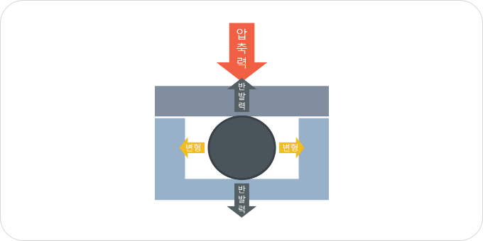
01
A seal generated by the restoring force from O-ring compression
When the O-ring is compressed and deformed, a restoring force is generated,
eliminating the gap in the groove and enabling sealing.
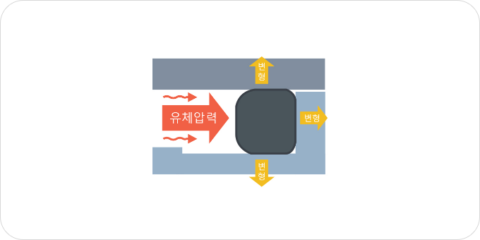
02
A seal generated by O-ring deformation due to fluid pressure
The pressure of the working fluid (liquids or gases such as oil, water, or air)
deforms the O-ring, eliminating the gap in the groove and allowing for sealing.

Pay attention to two factors: compression ratio of 8–30% and gland fill of 60–90%.
Set the groove height based on the compression ratio and adjust the groove width according to the gland fill.

The compression ratio refers to the percentage by which the O-ring is compressed in the groove.
If the compression ratio is too low, sufficient restoring force cannot be
generated, leading to sealing failure. Conversely, if the compression ratio is
too high, there is a higher risk of O-ring damage.
(See the calculation formula)
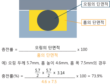
Gland fill refers to the ratio of the O-ring cross-sectional area to the groove cross-sectional area.
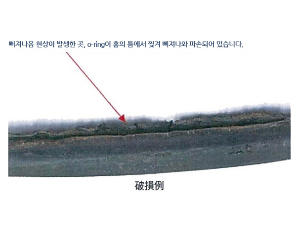
If the gland fill is too low, the O-ring may move within the groove, causing
problems. Conversely, if the gland fill is too high, the O-ring may protrude
from the groove and become damaged, or it may not be compressed
sufficiently, leading to sealing failure. (See the calculation formula)
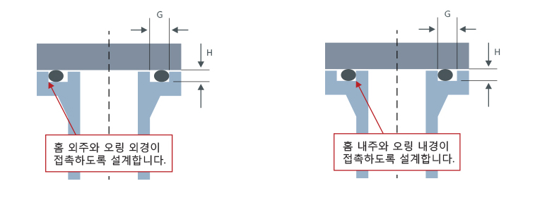
O-rings for Dynamic and Static (Radial Compression) Applications
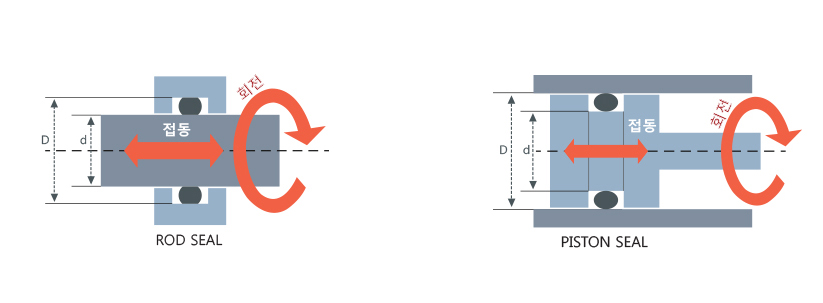
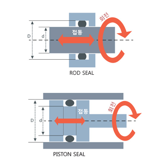
Dynamic: reciprocating, rotary
Static (radial compression)

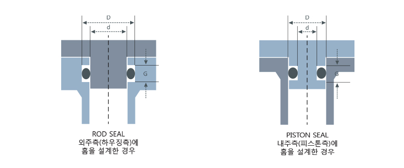
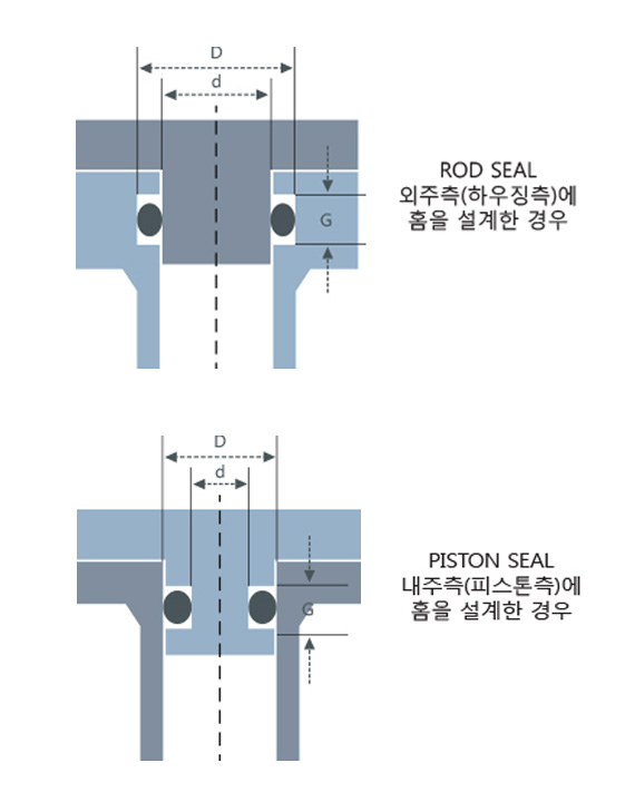
Under these usage conditions and design (clearance), extrusion may occur
For countermeasures against extrusion, please refer to the following.
| O-ring standard thickness d |
Groove height (D-d)/2 |
Groove width G | ||
|---|---|---|---|---|
| No back-up ring | One back-up ring | Two back-up rings | ||
| 1.9 | 1.5 | 2.5 | 3.9 | 5.4 |
| 2.4 | 2.0 | 3.2 | 4.4 | 6.0 |
| 3.1 | 2.5 | 4.1 | 5.6 | 7.3 |
| 3.5 | 3.0 | 4.7 | 6.0 | 7.8 |
| 5.7 | 5.0 | 7.5 | 9.0 | 11.5 |
| 8.4 | 7.5 | 11.0 | 13.0 | 17.0 |
※ Examples of cross-sectional dimensions for grooves fixed on cylindrical surfaces and dynamic applications (reference standards)
※ The groove inner diameter is set to be almost the same as the O-ring inner diameter (nominal size), increased by about 0.2–0.3 mm.
※ Thicknesses 4.0, 6.0, and 10.0 belong to the V series (for vacuum use); there are no groove design settings for fixed on cylindrical surfaces or dynamic use.
Extrusion and Countermeasures (Determining the Use of Back-up Ring)
The groove design for fixed on cylindrical surfaces and dynamic use inherently has clearances.
Depending on groove design (maximum diameter clearance, housing gap),
fluid pressure, O-ring hardness, and other factors, extrusion may occur.
Whether extrusion occurs is determined by a graph. If extrusion occurs,
the following countermeasures can be considered and selected according
to the situation.
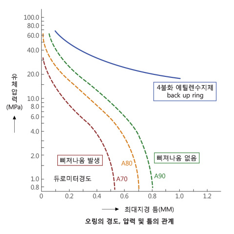
Relationship Between O-ring Hardness, Pressure, and Clearance
Please note that the values in the illustration do not account for housing
expansion due to fluid pressure. (Generally, it is recommended to design
the clearance to be 75% or less of the values shown in the illustration,
considering expansion.)
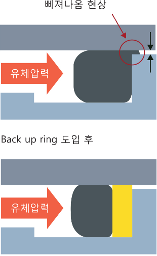
Installing a back-up ring to prevent extrusion
A clearance (maximum outer diameter clearance) occurs between the outer
side (housing) and the inner side (rod or piston). If the clearance is open,
the O-ring may extrude, causing damage and leading to leakage.

Fluid Pressure and Maximum Groove Outer Diameter Clearance
The vertical axis represents fluid pressure, and the horizontal axis represents
the maximum groove outer diameter clearance (housing clearance).
This chart indicates whether extrusion occurs or not for hardness levels 70,
80, and 90, as well as when a backup ring is used. For example, in the left
diagram, the extrusion judgment for hardness 70 is shown with color coding.
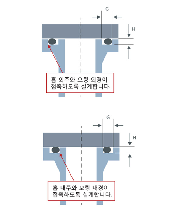
Used for flat (flange) mounting
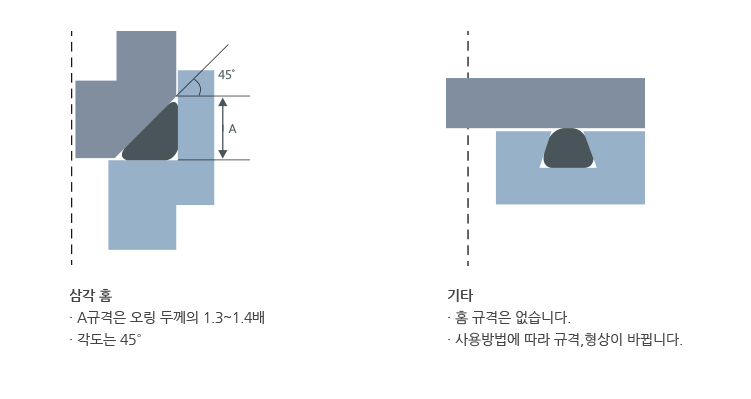
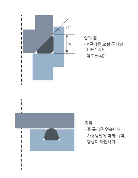
Other groove designs (triangular groove, other grooves)