Technical Information
Defects and Countermeasures
Oil seal
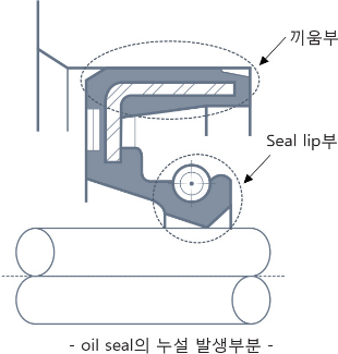
Leakage factors from the lip
-
01
Excessive lip wear
Insufficient lubrication, foreign matter intrusion, high internal pressure, rough shaft surface
-
02
Lip wear
Significant handling misalignment, tilted installation
-
03
Lip hardening
Abnormal high temperature, high internal pressure, insufficient lubrication
-
04
Lip softening
Inappropriate lip material
-
05
Lip damage
Improper assembly, mishan dling, poor shaft chamfering, foreign matter intrusion
-
06
Lip recess breakage
Improper assembly, excessive internal pressure
-
07
Lip inversion
Poor shaft chamfering, improper assembly, high internal pressure
-
08
Spring dislodgement
Poor shaft chamfering, Improper assembly
-
09
No defect in the oil seal
Shaft damage, shaft directiona lity, excessive shaft eccentricity, shaft wear, reverse installation
-
10
Oil seal deformation
Improper assembly
Leakage at the lip (inner circumference)
| Factors | Failure mode | Causes | Countermeasures | |
|---|---|---|---|---|
| Excessive lip wear | Lack of lubrication |
Significant wear is evident at the lip edge, and the worn surface has lost its gloss. |
When the lubricant level is below the specified amount, oil does not reach the lip, resulting in dry operation and abnormal wear. The structure near the oil seal is poor, preventing oil from reaching the lip. | Operate by supplying lubricant up to the specified amount. |
Examples
|
Examples
|
|||
| Foreign matter intrusion |
Significant wear is present at the lip edge, characterized by scratches and indentations. |
Using a shaft or oil seal with attached cutting debris causes the cutting powder to embed in the lip. 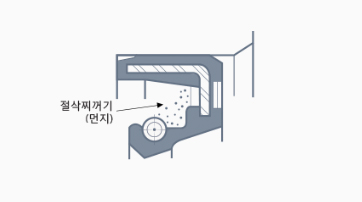
Using an oil seal on a shaft with dust or particles causes them to embed in the lip. Using a liquid gasket attached to the lip or shaft causes it to catch at the lip edge. During equipment painting, if paint adheres to the lip or shaft, it causes chewing damage. |
Assemble so that dust or particles do not adhere to the oil seal or shaft. When cleaning equipment, use the lubricant intended for use. | |
| High internal pressure |
Significant wear is present at the lip edge, characterized by scratches and indentations. |
The pressure at the oil seal exceeds the design value. | Change to a high-pressure oil seal. Design a breather to create a structure that does not apply pressure. | |
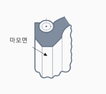
| Excessive shaft surface roughness |
Significant wear is present at the lip edge, and the worn surface shows circumferential scratches. |
Abnormal wear occurs due to using a shaft rougher than the specified surface roughness of Rmax 0.8 to 2.5 μm. | Correct the shaft surface roughness to Rmax 0.8 to 2.5 μm using emery paper (around #240 grit). Never move the emery paper in the shaft’s axial direction. Replace with a shaft that meets the specified roughness. | |
| Uneven lip wear | Large handling eccentricity |
The lip operating width is not uniform around the circumference, with the positions of the minimum and maximum widths almost opposite each other. |
Operated with the shaft and housing misaligned during assembly. | Increase the concentricity accuracy between the shaft and housing. |
| Operated with the shaft bent in one direction. | Increase the shaft strength against bending. | |||
| Tilted installation |
The lip operating width is uneven around the circumference, with the positions of the minimum and maximum widths nearly opposite each other. The relationship between the operating widths of the seal lip and dust lip is reversed. |
The housing's inner diameter was finished smaller than the specified size, forcing the oil seal to be inserted at an angle. | Use housing that meets the specified standards. | |
| The housing chamfering was either not done properly or was insufficient, or the oil seal was forcibly inserted, causing the oil seal to be installed at an angle. | Perform or correct the housing chamfering to the proper size. | |||
| The assembly jig was tilted, resulting in an angled installation. | Improve the assembly jig. | |||
| Lip hardening | Abnormally high temperature |
The lip operating surface is smooth and glossy, but the entire lip has hardened, resulting in lip cracks. |
The oil temperature near the seal lip rose due to some cause, exceeding the rubber's heat resistance limit. | Investigate the cause and prevent the temperature rise. |
| The oil temperature exceeded the heat resistance limit due to conditions differing from those assumed during design. |
Examples
|
|||
| High internal pressure |
The pressure exceeded the oil seal's pressure resistance limit. |
The pressure exceeded the oil seal's pressure resistance limit. | Replace with a high-pressure oil seal. Design a breather to prevent pressure buildup. | |
| Lack of lubrication | The lip contact area is smooth and glossy, with cracks occurring on the lip contact surface or forming when pressed with a finger. In many cases, only the contact surface becomes hardened. | The lubricant was used in an amount below the specified amount, resulting in insufficient oil flow to the lip and causing a lack of lubrication. | Supply lubricant to the specified level before operation. | |
| Due to splash lubrication, only a small amount of oil reached the lip, resulting in a lack of lubrication. | As an emergency measure, switch to a dust lip type and apply grease between the lips. As a permanent solution, modify the structure near the oil seal to ensure sufficient oil reaches the lip. | |||
| Lip softening | Inappropriate lip material | The lip is swollen and softened. |
The lip material was not properly selected for the lubricant, resulting in swelling of the lip. | Replace with an oil seal made of a lip materialthat does not swell in the lubricant. Alternatively, change to a lubricant that does not cause the lip material to swell. |
| Swelling also occurred when the seal was immersed in cleaning oil or gasoline or when cleaning fluid remained on the seal after washing and it was left unattended. | Do not clean the oil seal. | |||
| Lip damage | Improper assembly | The lip sliding surface is smooth and glossy, and the entire lip has hardened, showing cracks. | When the oil seal passed over a keyway or spline, it came into contact with a sharp edge, causing scratches. | Cover the keyway or spline with a cap to prevent scratches. |
| Scratches occurred because the oil seal was installed while burrs remained on the chamfered section of the shaft. | Remove burrs and other residues. | |||
| Mishandling | During transport or storage, the lip came into contact with a sharp metal part, causing damage to the lip edge. | Improve transport and storage methods. | ||
| Damage to the lip edge occurred due to handling the oil seal with gloves contaminated with metal shavings. | Do not touch the lip edge. | |||
| Improper shaft chamfering | Visible scratches are present at the lip edge. | The chamfer dimension and angle at the shaft end were inaccurate, causing the lip to catch on the shaft end and become scratched. | Properly chamfer the shaft. | |
| Foreign matter | Foreign matter is attached to the lip edge. There are indentations on the lip sliding surface. | Metal shavings entered the lip edge when a shaft contaminated with cutting debris was used. Metal shavings became embedded in the lip edge due to the use of parts contaminated with metal powder. Foreign matter entered the lip edge from prolonged use of shafts or oil seals left in dusty environments. | Clean the equipment. | |
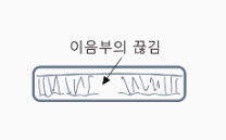
| Lip reversal | Poor shaft chamfering | Part of the lip twists in the opposite direction when the oil seal is inserted onto the shaft. | The chamfer dimensions and angle at the shaft end were not appropriate, causing the lip to catch on the shaft end and flip over. | Assemble by properly adjusting the chamfer dimensions and angle of the shaft end and applying grease to the chamfered area. |
| Improper assembly | The lip twisted due to careless assembly that failed to align the centers of the shaft and housing. | Remove burrs and carefully assemble the lip by aligning the centers of the shaft and housing holes. In this case, apply grease to the shaft end. | ||
| High internal pressure |
A portion or the entire circumference of the lip is turned outward (reversed). |
During the operation, abnormally high pressure applied a large force to the lip area, causing the lip to twist. | Modify the structure so that pressure is not applied, and use a high-pressure oil seal. | |
| Lip recess breakage | Improper assembly |
There are cracks in the lip recess. |
During assembly, the lip was deformed, causing cracks in the recess. | Assemble carefully by aligning the centers of the shaft and housing. |
| Excessive internal pressure | After assembly, excessive pressure during the pressure test (airtightness test) caused cracks in the recess. | Do not perform tests at pressures exceeding the oil seal’s rated pressure. | ||
| During the operation, high pressure exceeding the design expectation occurred, causing cracks in the recess. | Change to a high-pressure oil seal and modify the structure to prevent excessive pressure. | |||
| Spring dislodgement | Poor shaft chamfering | The spring is partially or completely dislodged. | The chamfer dimensions and angle at the shaft end are improper, causing the lip to catch on the shaft end and the spring to dislodge. | Assemble by properly adjusting the chamfer dimensions and angle of the shaft end and applying grease to the chamfered area. |
| Improper assembly | During assembly, careless assembly without aligning the centers of the shaft and housing holes caused the spring to dislodge. | Carefully assemble by aligning the centers of the shaft and housing holes. In this case, also apply grease to the shaft end. | ||
| Oil seal deformation | Improper assembly |
The oil seal is deformed, causing a change in the lip operating width at the deformed area. |
The oil seal assembly jig is inappropriate, causing deformation of the oil seal. | Improve the assembly jig. |
| No abnormalities in the oil seal | Shaft scratches | Visible scratches are present on the shaft's operating surface. | Insert a support into the oil seal to shift the operating position.Rework the damaged area. | |
| Shaft directionality | The shaft was used as-is after turning (lathe) machining. | Carefully finish only the shaft lip operating surface with emery paper (#240) to avoid scratches. | ||
| Scratches occurred due to grinding or the use of emery paper during finishing machining. | Change the finishing method to one that doesnot cause scratches in the shaft direction. | |||
| Shaft eccentricity | Shaft eccentricity increased beyond the design value due to bearing abnormalities. | Replace the bearing. | ||
| A general-purpose oil seal was used despite significant shaft eccentricity in the mechanism. | Replace with a special oil seal designed for high eccentricity. | |||
| Shaft wear | An oil seal contaminated with dust and cutting chips was installed. Oil deterioration and foreign matter intrusion caused external contaminants to enter the lip operating area. | Clean the equipment and insert a support into the oil seal during assembly to prevent damage to the operating area. If the dust amount is minor, use an oil seal with a dust lip or attach a dust cover. | ||
| A general-purpose oil seal was used despite significant shaft eccentricity in the mechanism. | Use appropriate shaft materials. | |||
| Shaft handling in the opposite direction | Incorrect installation during assembly. | Install the seal lip with its direction facing the sealed side. | ||
Leakage at the bore seat (outer circumference)
| Factors | Failure mode | Causes | Countermeasures |
|---|---|---|---|
| Tilted installation |
|
The housing bore was finished smaller than the specified dimension, and the oil seal was forcibly inserted, causing it to be installed at an angle. | Ensure that the housing bore inner diameter meets the specified dimension. |
| The housing bore was either not chamfered or improperly chamfered, and the oil seal was forcibly inserted, resulting in a tilted installation. | Chamfer the housing bore or ensure it is made to the proper dimension. | ||
| The assembly jig was tilted, leading to a misaligned installation. | Improve the assembly jig. | ||
| Deformation |
Part of the outer diameter (OD) surface shows localized breakage. |
The oil seal was deformed due to an inappropriate assembly jig. | Improve the assembly jig. |
| An oil seal that had been partially deformed during handling was assembled, resulting in a gap at the outer diameter (OD) section. | Take care during handling to avoid dropping the oil seal or striking it against hard objects. | ||
| Galling or tearing of the outer diameter (OD) section |
|
The inner diameter of the housing bore was finished smaller than the specified dimension, and the oil seal was forcibly inserted, causing it to be installed at an angle and resulting in damage to the outer diameter (OD) section. | Finish the housing bore to the specified inner diameter dimension. |
| The housing bore was either not chamfered or improperly chamfered, and the oil seal was forcibly inserted, resulting in damage to the outer diameter (OD) of the oil seal. | Chamfer the housing bore or adjust it to the appropriate dimension. | ||
| The oil seal was installed without proper parallel alignment between the oil seal assembly jig and the housing, causing damage to the outer diameter (OD) section of the oil seal. | Ensure parallel alignment between the oil seal assembly jig and the housing. | ||
| No abnormalities in the oil seal | Damage occurred on the housing bore inner surface due to the installation of the oil seal with foreign matter, such as cutting chips attached to the housing bore inner surface or oil seal bore seat. Damage occurred on the inner surface of the housing bore due to repeated assembly and disassembly of the oil seal. There is significant damage to the inner surface of the housing bore. | Apply a thin layer of liquid gasket to the inner surface of the housing bore to fill the damage. However, take care to avoid the liquid gasket attaching to the oil seal lip or the shaft. | |
| Scratches occurred on the housing bore inner surface due to installation without removing burrs from the housing bore surface treatment area. | Remove the oil seal and check for burrs on the chamfered part of the housing bore. If burrs are present, remove them with emery paper and apply a liquid gasket to the inner surface of the housing bore. | ||
| The roughness of the housing bore inner surface is severe. |
Emergency measure
|
Examples of oil seal leakage and misidentification
-
01
Leakage at the equipment mating surface
Permanent deformation of the gasket, loose bolts, damage to assembled parts
- 02 Cracks in the equipment body or cover parts, casting leakage
- 03 Oil contamination on the mating surface of the housing or oil seal during assembly
- 04 Leakage of the initial lubricant for the oil seal